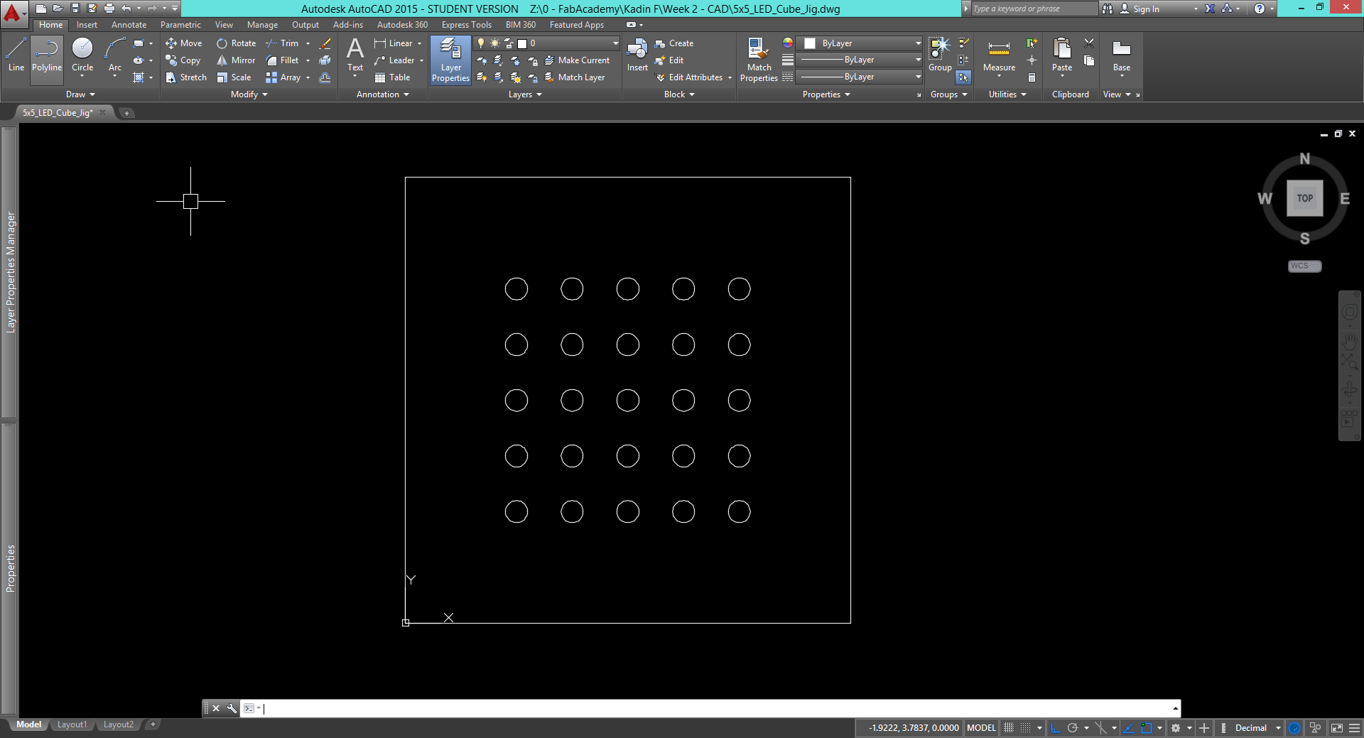
I started my 2d design this week in AutoCAD(although I plan to try out some different, open source softwares). The drawing above is a jig for soldering my LED cube together. It is a simple 4" square with a pattern of 5mm holes. When I assemble my LED cube I will place a 5mm LED in each hole so the cathode and anode pins are facing up. I will then bend the anode pins 90 degrees so that each LED is connected to the next making one layer of the cube. I will need 5 layers for the cube to be completed. |
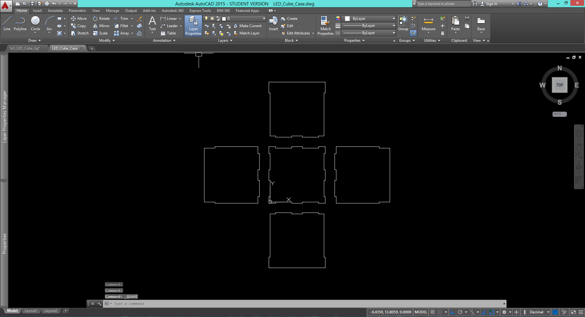
Next I designed the case for the LED cube in AutoCAD. I plan to laser cut it out of clear acrylic to show off the cube as well as protect it. The case will notch together and eventually set in a 3d printed base. The 3d printed base will hold a custom milled PCB designed in Eagle that will serve as the brain of the cube. In the future I will add variables to this design in AutoCAD. This will allow me to adjust the size of the physical box itself as well as the notchs. By doing this I will be able to easily change the box to work with any thickness of material and size of cube. |
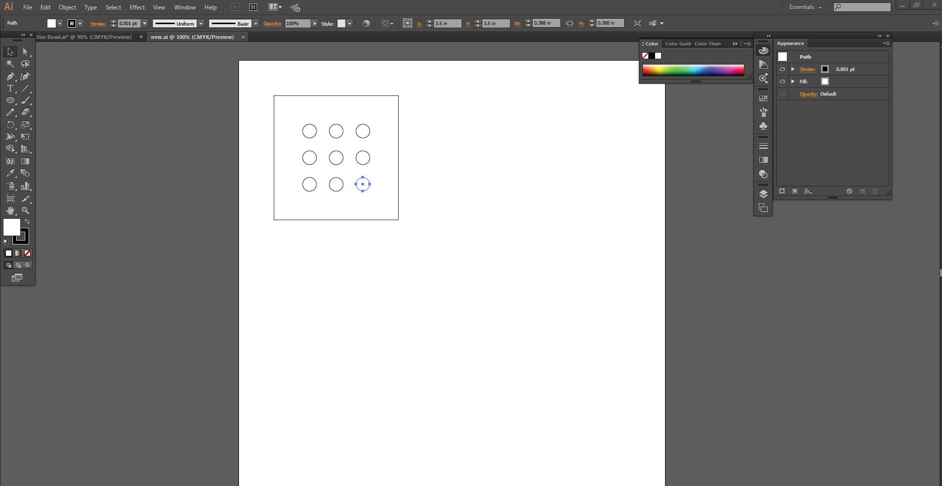
After designing the case and jig for my larger LED cube I decided to start on a smaller 3x3x3 LED cube. The first step was designing a jig for the smaller cube, so I tried out Adobe Illistrator. I made a 4" square and added nine 10mm holes for the LEDs to sit in. While using Adobe Illustrator I noticed a few key differences between it and AutoCAD. The main difference is speed, in Illustrator it takes much longer to design a simple part. This is mainly because of the keyboard shortcuts available in AutoCAD. Next I will laser cut my part desgined in Illustrator to make a mini model of what my final project might look like. |
Below are the steps seen in the video above. |
Start by creating a new acad.dwt document using the menu in the upper lefthand corner of the screen.
Then turn "ortho" mode on. You can do this using a keyboard shortcut or by typing in the command line at the bottom of the screen. Ortho mode ensures that all lines you draw snap to vertical or horizontal, making it easier to create squares and rectangles.
The draw a square by either typing or selecting with your mouse the line tool. Type "0", "space", "0", "space" to tell Autocad to start your line at the origin. Then move your mouse upwards and your line should snap to vertical. You can then type a length and hit space to finish the line.
Once thats done do the same thing but with a circle. This time use something like 0.5, 0.5 so that the center of the circle is inside the square.
Next, select the array tool and create an array of circles inside of your rectangle. You can choose any size array you want, you are only limited by the size of your original square, which you can change at any time
Lastly, save your document.
Above is a video outlining the basic process for creating a drawing in AutoCAD. The thing that I like most about AutoCAD is the speed at which you can do simple tasks once you before proficent. There are lots of keyboard shortcuts and with some practice you can do almost everything with the keyboard saving you time on large projects. The most time is saved by eliminating the need to sort through menus to find the exact tools and functions you would like. |
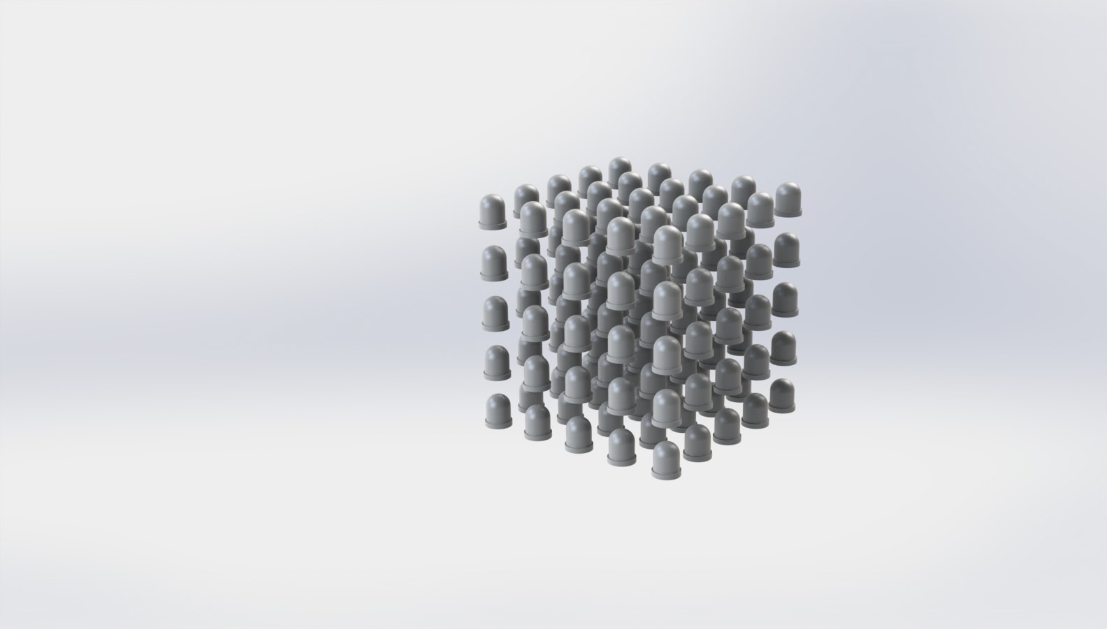
For 3d design this week I used SolidWorks. I created a three dimensional cube of 125 LEDs and used the rendering software to create a decent quality photo. This model has helped give me an idea of the space I will have to solder the LEDs together. I think based on the model I will definetly opt for small 5mm LEDs rather than the 10mm LEDs I used in my SolidWorks model. This will give me more spacing for wiring and make it easier to see the lights on the inside of the cube. |
Below are the steps seen in the above video. |
Start by using the menu under "file" to create a new file, and select "part".
Then right click on the top plane and click create sketch. Select the rectange tool and place a rectangle near the orgin.
Using the dimension tool under the sketch tab add dimensions between the center of the rectangle and the orgin to position it. You can also add dimensions to the rectangle's sides to resize it.
Next, select the linear sketch pattern tool in th sketch tab and create a pattern of the disired size, selecting the sides of your rectangle as the "Entities to Pattern"
Then open the "features" tab and select extruded boss base. In the extrude tool you can set the extrusion height of your rectangles and select any number of them to include/disclude.
Now you have a 2d array of 3d objects, to turn this 2d pattern into a 3d pattern select the linear pattern tool under the features tab. Select your 2d array as the "Features and Faces" to pattern. Again, you can change the size of the pattern to your liking.
Lastly, under the "Solidworks Add-Ins" tab you can select Photoview 360 and create a more realistic rendering of your model, then save your document if you have not already done so.
Overall this video outlines the process for creating a 3d pattern such as the LED cube render above using Solidworks. Solidworks is my go to 3d design program do to its plethora of features and easy to use, logical interface. It provides everything from basic geometric design to advanced surface modeling and parts testing. |